Showing posts with label Technology. Show all posts

03 December 2011

Sanyo Eneloop 2-AA NiMH Pre-Charged Rechargeable Batteries with USB Charger


Price: $10.99
amazon button

Product Description

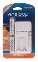
This Sanyo Eneloop Rechargeable Battery package includes 2 AA-size batteries and a handy USB charger. The batteries come fully charged, and once drained can be quickly charged again. NiMH technology gives them the ability to be charged up to 1000 times without experience battery memory effect.

Product Details

  • Color: White
  • Brand: Sanyo
  • Model: SEC-MDU01-2AA-TG
  • Number of items: 1
  • Dimensions: .60" h x 3.30" w x 6.00" l, .38 pounds
  • Battery type: NiMh

Features

  • Travel charger plugs into the USB port of your computer
  • Charges AA batteries in 4 hours and AAA batteries in 2 hours
  • Eneloop batteries come pre-charged and ready to use
  • Take over 4.4 times as many digital pictures than standard alkaline batteries
  • Can be charged up to 1000 times using the latest NiMH industry technology available
Auto Post

14 October 2011

A Bright Introduction To Fiber Optics Technology

Understanding how fiber can be produced and function for use in daily life is a fascinating work of art with science. The optical fiber was built with materials that are light to pass and were included in a package of very thin glass or plastic fibers in a tube. One end is connected to a light source and the other end has a camera lens, used for light and images in the curves and corners of the chain. The optical fibers surrounding a core of highly transparent glass or plastic cover as a "sham." Light is excited by a source at one end of the fiber and the light propagates through the tube, the coating is to do everything inside. A bundle of glass fibers can be bent or twisted without distorting the image, because the panel reflected the images of the interior lighting of the area. The fiber optic light source can carry light over a distance of ground, from a few centimeters over 100 miles.

There are two types of optical fibers. The single-mode fiber is used to transfer high-speed, long distance, because they have very small cores and accept light only along the fiber axis. Send small laser fiber directly into the light where there is little loss of connectors used to attach the fiber in the system without significant degradation of the light signal. Then there is Multi-Mode, which have much more cores and accept light from different angles and can use different types of light sources. Multi-mode fiber connections even cheaper, but can not be used over long distances, as in the single-mode fiber.

Optical fibers have a wide variety of applications. Common and are used in communication systems, fiber optic communication systems have a variety of features that make it better than systems that use traditional copper cables. The use of fiber optics with these systems use a higher-capacity data transport because they are not harassed by electrical interference and require fewer amplifiers then the copper cable systems. Fiber optic communication systems have been installed in large networks of fiber bundles around the world and even under the oceans. Many fiber optic testers are available to provide the best equipment of optical fibers.

Optical communication systems fiber, lasers are used to transmit messages in numeric code by flashing at high speed. This code can be a voice or an electronic document containing text, numbers or images, all with optical fibers. Laser light are added to many on a single fiber optic enabling thousands of currents to pass data over a single fiber optic cable at a time. These data passes through the fiber optic equipment and interpretation to convert messages back to the shape of the original signals. Industries for the optic fiber pressure, temperature measurement, and acceleration voltage used in a variety of others.

20 March 2011

Access Control: An Introduction To Access Control

The Problem

Your building is secure at night, but during the day there are several doors that have to be open. Anybody could walk in. What can you do?

The Solution

You need an Access Control System.

What is an Access Control System?

Access Control is an electronic security system which permits or restricts access to specific areas of a premises. It not only protects property against unwanted visitors but ensures the safety of both the property and of the people inside.

In simple terms, an Access Control System provides control of entry (or exit) through nominated doors via a control panel and some form of electric locking facility.

An Access Control System can be as simple or as complicated as you wish but in each case, the solution will always provide an easy passage for permitted persons around the building.

Door Entry or Access Control?

Door entry is commonly associated with a single door or gate, whereas access control is more suited to multiple doors or entry points.

Access Control can also incorporate a host of other features which enhance other areas of the business.

Access Control / Door Entry Technology

There are a number of ways that a permitted user can open a door that is fitted with a system.

PIN Code Entry

The most common unit is the keypad system. This comprises a control unit with a series of numbered push buttons, or a touch-sensitive pad, connected to the lock release mechanism via a control unit located at the entrance.

Magstripe (also called Swipe Card) Readers

Each entry point has a card reader and the user “swipes” an encoded card similar to a credit card to gain entry.

This technology is widely used and there are many choices of manufacturers.

Proximity Readers

Rather than swiping the card or tag, it is simply presented to a reader which typically will see the card at a distance of about 100mm. This is a fast, non-contact, method of entry.

Long Range Readers

Long range proximity readers (of approximately a meter or so) automatically unlock or open a door when it detects the card.

This is particularly suitable for compliance with the Disability Discrimination Act  (DDA) as no action is required by the card bearer.

Smartcard Readers

For systems that use cards or tags, these cards can also carry additional information which can be used for other building services – – for example, time and attendance functions, integration with payroll systems, car park management and even vending machine applications.

Biometric Readers

A Biometric Reader system uses unique human characteristics – such as finger prints or a retina scan – to clearly identify those who are permitted access.

As there are no cards or tags which can be stolen or lost, or open to misuse, this type of system significantly increases the level of security.

What about Visitors?

You will want to welcome most of those who visit your premises, so it must be easy for them to let you know they are there.

The three most common means of attracting attention are:

• A simple door bell system which alerts your staff to the fact that there is someone waiting outside.

• An audio intercom panel which allows the visitor to have a direct conversation with a member of your staff and, if appropriate, the door can be remotely released.

• An audio intercom panel with a camera facility which allows your staff to see who wants to enter the building before permitting access.

Once access has been permitted, the visitor can either be escorted around or issued with a card or pin number for the duration of their visit.

Things to Consider

When planning an access control system, you should consider the following:

• How many entry/exit points
• Where are these located>
• Level of security desired
• The movement of staff around the building
• Method of operation
• Future growth of building
• Turnover of employees
• Disability access
• Interface with other systems – for example, the fire alarm

As with any type of security system, it is sensible to employ a company that you can trust. Make sure you use a NSI (NACOSS) approved organisation; this will ensure that your system will be designed and installed by professionals.

11 March 2011

MRI Scan: A Guide To Mri Scans

As soon as Computerized Tomography or CT scans became accessible in the 1970s, they reformed the practice of neurology. They did the scans by transmitting x-ray streams all the way through the head at different positions and accumulating the x-ray streams on the other side that was not absorbed by the head. A sequence of images come into view on a computer monitor or on an x-ray plate as if the head had been sliced from side to side by a huge salami cutter and the slices were arranged out horizontally and in series.

After that, in the 1980s Magnetic Resonance Imaging or MRI scans came into the picture and astounded the medical society by not just taking an image of the brain itself, but by doing so in a new way. MRIs concentrate on water molecules, as an alternative to imaging the degree to which the various parts of the head absorb x-rays. To be more specific, MRIs represent the speed at which rotating hydrogen atoms of water molecules inside various parts of the brain either line up or fall out of arrangement with a powerful magnetic field. These different values of de-magnetization or magnetization are inputted into a pc. Slice like images are formed in a sequence and put on view on a computer screen or x-ray type film in hues of gray. Irregular compositions, like brain tumors or the signs of multiple sclerosis, are shown in their own hues of gray and are also identifiable by their contours and positions. More on this at http://www.medicalimagingdevices.info. Getting hold of a different set of images after a hypodermal injection of gadolinium, which is the MRI equivalent of x-ray dye, also adds to analytical information.

For a patient, the incident of having a CT and of having an MRI very much looks a lot like each other. In both situations the patient lies flat on a plane table that moves into and out of a hole in the scanner that looks a lot like an oversize doughnut hole. In the MRI machine the doughnut hole is narrower, so patients suffering from claustrophobia have to notify their doctors if this might be a hitch. Noise is also an issue with the MRI machine. A loud noise is produced every time the radio frequency coils are turned off and on. For either of these two scans the technologist may need to inject a needle in the patient's vein to dispense a distinct substance.

A situation in which MRIs are basically not done is when the patient has a heart pacemaker. This is for the reason that the MRI machine's magnet might disturb the pacemaker and stop the heart. No image is so essential and important that this peril would be worth taking. Another situation in which an MRI is evaded is when the patient is gravely ill. A serious patient can be effectively examined and sustained while getting a CT scan, but not while getting an MRI.

10 March 2011

A Concise Guide To MICR And Associated Technologies

Magnetic Ink Character Recognition (MICR) was developed to utilize the benefits of computer technology in the banking industry. Prior to the use of a MICR line, check sorting by account number was a manual process. Two systems were previously used to handle the large numbers of checks processed in the banking industry: Sort-A-Matic and Top Tab Key Sort.

The Sort-A-Matic system included 100 metal or leather dividers numbered 00 through 99. Each check was placed in the corresponding divider by the first two numbers of the account. The sorting process was then repeated for the next two digits of the account number, and so on. When the process was complete, the checks were grouped by account number.

Under the Top Tab Key Sort system, small holes punched at the top of the checks indicated the digits. For instance, the first hole indicated the value of the first digits (0, 1, 2, 3...) A metal "key" was inserted through the holes to separate all of the checks with the same value in the first digit, and this step was repeated for each digit until all the checks were sorted.

Both of these systems worked, but they were time-consuming. With the advent of the computer and its movement from the laboratory into the business world, a sorting and matching task seemed ideal. Stanford University and Bank of America were the first to successfully use computers to sort and match checks. They developed what is now known as MICR.
The Development of the MICR Font

The MICR font was developed by Stanford University in conjunction with Bank of America and approved by the American Banking Association. The font is known as the E-13B font. E-13B has a total of 14 characters: ten specially designed numbers (0 through 9) and four special symbols (Transit, Amount, On-Us, and Dash).

The letter E indicates the fifth version considered. The letter B indicates the second revision of that version. The number 13 is derived from the 0.013-inch module construction used for stroke and character width. This means that all character widths, both horizontal and vertical, are in multiples of 0.013 inches ranging from 0.052 to 0.091. The significance of this will be explained more thoroughly later in this article.
MICR Readers

Three types of machines are used to read MICR characters. The two that read the characters magnetically are referred to as MICR readers. The third machine is an Optical Character Recognition (OCR) reader.

E-13B characters are printed with toner containing iron oxide, which is capable of being magnetized. MICR readers transport the checks containing the E-13B magnetic characters past a magnet, thereby magnetizing the iron oxide particles. The magnetized characters then pass under a magnetic read head. The magnetic field (flux pattern) caused by the magnetized characters generates a current in the read head. The strength and timing of this current allows the reader to decipher the characters.

Magnetic readers come in two types: single track (single gap or split scan) and multiple track (matrix or pattern) readers.

Single-Track Reader Characteristics
Single track uses a read head with one gap to detect the magnetic flux pattern generated by the MICR character. When a magnetized E-13B printed character moves across the narrow gap of the read head, the electric voltage caused by the magnetic flux from the character generates a waveform unique to each character.

Multi-Track Reader Characteristics
The multiple track reader employs a matrix of tiny, vertically aligned read heads to detect the presence of the magnetic flux pattern. The small individual read heads slice across the character to detect the presence of magnetic flux. This sensing of magnetic flux over time produces a unique matrix pattern for each character.

An OCR reader does not use magnetic properties to detect the E-13B characters. Instead, it uses a scanner to detect the amount of light reflected from the character and the amount of light reflected from the background. A photocell column detects the presence of the dark area of a character.
Waveform Theory

The readers move and read documents from right to left. The right-hand edge of the character, as a result, is the first to cross the read head. Analysis of the signal level created by reading the character 0 will help explain this in greater detail.

As the character moves from right to left under the read head, the gap detects the magnetism of the first right-hand edge (edge 1). This results in the increase in magnetism and a positive peak is created (peak 1). As soon as the right-hand edge moves beyond the read head gap, no new magnetism is found, and thus the wave form returns to the zero signal level.

At the second edge, the vertical read head detects a drop in magnetism, which results in a -110 signal level at peak 2. Again the waveform returns to zero until the next portion of the inner ring of the character is detected. At this point (peak 3), an increase in magnetism (+110) is indicated. Finally, the outer portion of the character is read, resulting in a negative peak (peak 4) of -130.

The placement of the vertical edges must occur in increments of 0.013 inches from the first right-hand edge. There are five characters that have two positive and two negative peaks similar to the character 0 and also appear in a positive-negative-positive-negative format. They are 0, 2, 4, 5, and the transit character, which are differentiated from one another by the horizontal location of the peaks in the waveforms. The peaks do require different amplitudes, but ANSI standards allow them to vary from 50% to 200% of the nominal amplitudes (Canadian standards allow them to vary from 80% to 200% of the nominal amplitudes). This is why the placement of the waveform is so important and why the characters are shaped unusually.
What Affects the Signal Level?

Signal level can vary based on a number of factors. The amount of iron oxide (concentration) that is present in the character will affect the signal level. This is a function not only of the toner itself, but also of how it is laid on the paper and the pile height, which can be controlled by numerous other cartridge components (i.e., "hot" OPCs).

The taller the vertical edge of the character, the taller the peak (either positive or negative). A vertical edge that is not regular and/or not vertical will result in a reduction in the amplitude of the peak and will flatten the peak out.

Keys to proper waveform detection are:

* All peaks in a character's waveform must be detected. The reader sorter must know that the peak is there.

* The peak must be located at or near its anticipated location.

* No significant "extra" peaks can be present.

* There cannot be wide variations in the signal levels of peaks within a character.

What to Look for in MICR Printers and Consumables

Printers that are used for MICR printing must have a unique MICR font that is modified to suit the unique printer engine, and it must be modified to the pixel level to match the magnetic toner provided for that printer. This is essential to ensure the correct waveform, dimension, and signal strength when a check is printed with the correct MICR characters. In addition, the MICR font must meet ABA-X9 standards to ensure acceptance of your checks by banking institutions.

The magnetic MICR toner that you choose must be specifically designed for the particular print engine in the printer. Ensure the toner has been thoroughly tested for consistent signal readings, image permanence and uniformity, and excellent edge acuity. Toner coverage must be solid with no extraneous toner lay down.

OEM cartridges are always a safe (but more expensive) bet. If you buy a "compatible" brand, ensure it has a new OPC drum, new primary charge rollers (PCRs), a new black velvet magnetic sleeve, and new image wiper blades. The hopper system must be filled with high-quality, low-abrasion MICR toner.

The vendor you choose should use the latest and most advance MICR test equipment, such as a Verifier and Golden Qualifier to conform to ANSI X9 Standards. It is also recommended that the systems exceed U.S. and Canadian check printing standards.